LTE Cell Search Procedure
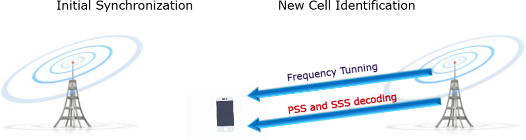
There are Two relevant cell search procedures exist in LTE:
Initial synchronization;
and New cell identification.
Initial synchronization, whereby the UE detects an LTE cell and decodes all the information required to register to it.
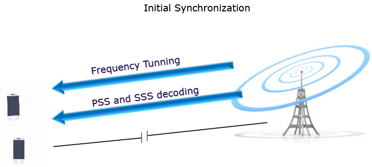
This would be required, for example, when the UE is switched on, or when it has lost the connection to the serving cell.
New cell identification, performed when a UE is already connected to an LTE cell and is in the process of detecting a new neighbor cell. In this case, the UE reports to the serving cell measurements related to the new cell, in preparation for handover.
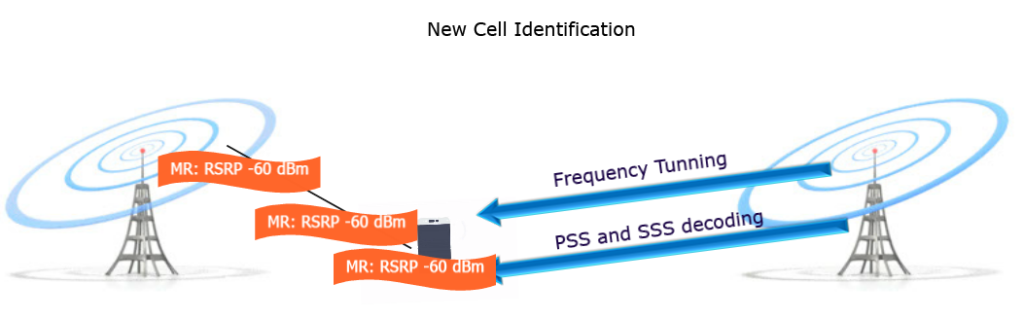
This cell search procedure is repeated periodically until either the serving cell quality becomes satisfactory again, or the UE moves to another serving cell.
In both scenarios, the synchronization procedure makes use of two specially designed physical signals which are broadcast in each cell:
the Primary Synchronization Signal (PSS);
and the Secondary Synchronization Signal (SSS).
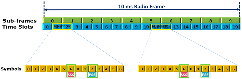
PSS and SSS Frame and Slot structure in time domain in LTE FDD:
The synchronization signals are transmitted periodically, twice per 10 ms radio frame.
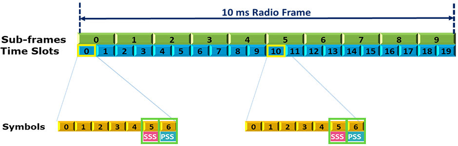
In an FDD cell, the PSS is always located in the last OFDM symbol of the first and 11th slots of each radio frame, and The SSS is located in the symbol immediately preceding the PSS
PSS and SSS Frame and Slot structure in time domain in LTE TDD:
In a TDD cell, the PSS is located in the third symbol of the 3rd and 13th slots, while the SSS is located three symbols earlier.
in LTE FDD, The PSS and SSS are transmitted in the central, six Resource Blocks (RBs), enabling the frequency mapping of the synchronization signals to be invariant with respect to the system bandwidth (which can vary from 6 to 110 RBs).
this allows the UE to synchronize to the network without any priori knowledge of the allocated bandwidth.
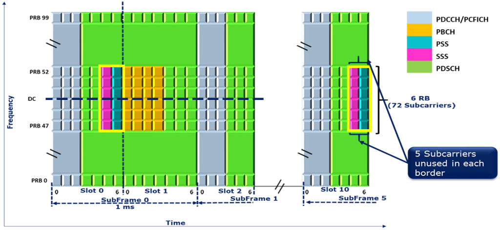
The PSS and SSS are each comprised of a sequence of length 62 symbols, mapped to the central 62 subcarriers around the D.C. subcarrier which is left unused. This means that the five resource elements at each extremity of each synchronization sequence are not used.
