LTE Downlink Power Calculation
The LTE standards do not specify how much power the various channels and reference signals should use, it is up to vendor to develop the appropriate algorithms and controls.
Power control regulates the transmit power of eNodeBs and UEs to compensate for path loss and shadow fading, counteract interference between intra-frequency E-UTRAN cells, and help meet coverage and capacity requirements.
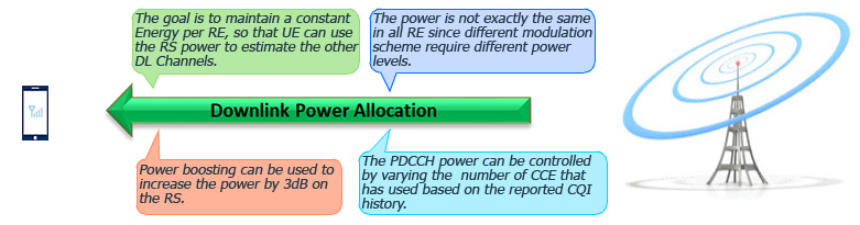
- The goal is to maintain a constant Energy per Resource element, so that UE can use the Reference signal power to estimate the other Downlink Channels.
- The power is not exactly the same in all Resource element since different modulation scheme require different power levels.
- Power boosting can be used to increase the power by 3dB on the Reference signal.
- The PDCCH power can be controlled by varying the number of CCE that has used based on the reported CQI history.
Downlink power allocation:
Downlink power allocation applies to the following physical signals, traffic channels, control channels, and messages using fixed and dynamic allocation:
Fixed Allocation:
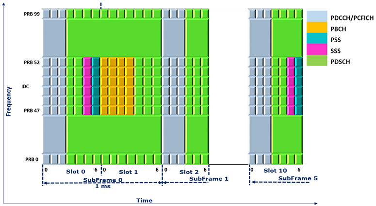
- Cell-specific reference signal (CRS);
- Synchronization signal PSS and SSS;
- Physical broadcast channel (PBCH);
- Physical control format indicator channel (PCFICH);
- Physical downlink control channel (PDCCH) carrying common control information;
- Physical downlink shared channel (PDSCH) carrying common information;
Dynamic Allocation:
- Random Access Response (RAR) messages;
- Physical HARQ indicator channel (PHICH);
- Physical downlink control channel (PDCCH) carrying dedicated control information;
- Physical downlink shared channel (PDSCH) carrying UE-specific information;
CRC Power
CRC are transmitted in all downlink subframes. They serve as a basis for downlink channel estimation and are used for data demodulation.
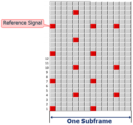
The CRC power is indicated by the energy per resource element, and is determined by the Reference signal power parameter.
The Reference signal power parameter specifies the reference signal (RS) power output by a remote radio unit (RRU).
For common scenarios, the RS power indicated in system information block type 2, namely Reference Signal Power SIB2 in the unit of dBm, is calculated using the following formula:

The number of physical antennas in a cell is specified by the Cell.TxRxMode parameter.
For 8T8R and 32T32R FDD cells, the RS power indicated in SIB2 is calculated using the following formula:

Power of PDSCH Type A & B
in PDSCH power setting, OFDM symbols in one timeslot can be classified into 2 types: type A symbols and type B symbols.
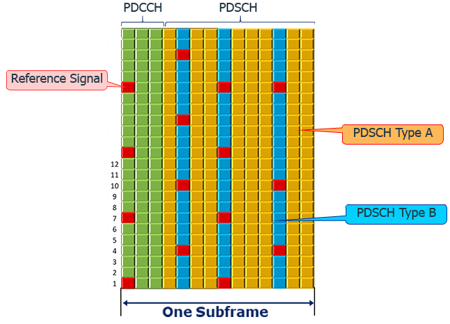
Type A: PDSCH resource elements where not in the same symbol as Reference signal resource element.
Type B: PDSCH resource elements in the same symbol as Reference signal resource element.
as described above the CRC power is defined by the reference signal power.
The power formulas for the PDSCH type A and B are defined as follow:
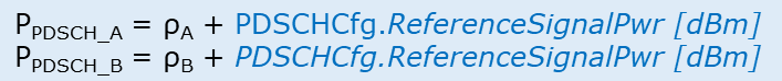
the rho A is calculated as follows:
delta power offset is specified by the parameter NPREO constant, acronym of nom PDSCH-RS-EPRE-Offset used for CQI optimization.
and P A, is defined by P A, for even power distribution parameter under cell downlink power control PDSCH PA.
rho B depends on the power factor ratio of rhoB/ rhoA.
The table lists the values of the cell-specific ratio rhoB/rhoA, corresponding to different PB values in scenarios with different quantities of antenna ports.

PB is specified by the Pb parameter under PDSCH configuration settings.
to calculate the PDSCH power for channels Type A and B, we need to calculate first the Reference signal power, which is given by the following formula:

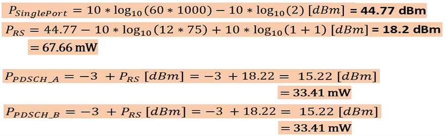
the power per single port is:

Calculation Example:
Bandwidth: 15 Mhz Antenna Ports: 2 Pa= -3 dB Pb= 1 RRU: 60 Watt
the power per single port is 44.77 dBm.

then the power per reference signal is 18.2 dBm.

the next step is to calculate rho A, and rho B.
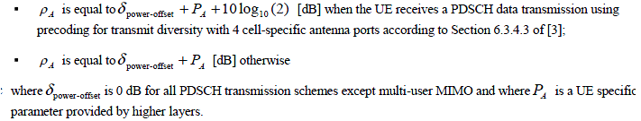
rho A is equal to.
delta power offset + Pa + 10 log 2. when the UE receive a PDSCH data transmission using precoding for transmit diversity with 4 antenna ports.
otherwise, rho A is equal to delta power offset + Pa.
as described in the preceding slide, delta power offset is the NEPRO value used for CQI optimization, in this example delta power offset is set to 0.
so, the rho A is the value of Pa parameter in dB, which define the difference between to dBm values.
PDSCH type A power and the reference signal power in dBm.
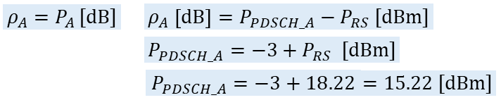
the power of PDSCH type A is equal to -3 + 18.22, = 15.22 dBm.
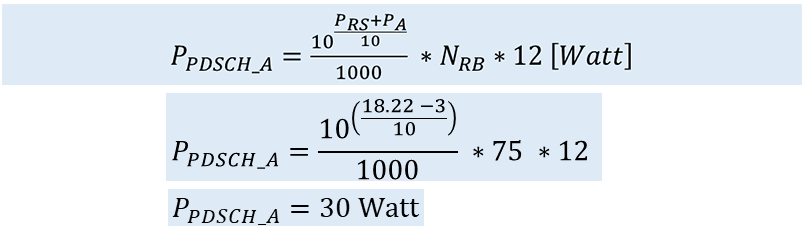
to use rho A as a ratio, to calculate the power in Watt, then rho A is defined by:
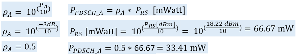
the rho A equal 0.5, and RS power is equal to 66.67 mWatt, then, the power of PDSCH type A is 33.41 mWatt.

to calculate the power of PDSCH type B, we need to calculate the value of rho B.
rho B depends on the power factor ratio of rhoB/rhoA.
The table lists the values of the cell-specific ratio rho B to rho, A, corresponding to different PB values in scenarios with different quantities of antenna ports.
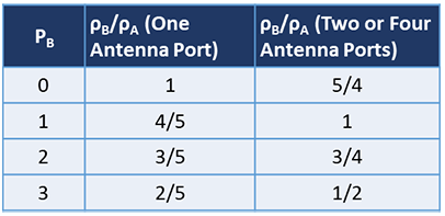
in our example Pb is 1, and Pa = -3 dB, and 2 antenna ports.
so, the ratio rhoB/rhoA is 1, then the rho B value is 0.5 as rho A equal to 0.5.
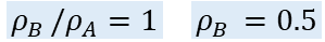
the current value of rho B can be used to calculate the power in mWatt.
for a calculation in dBm, rho B should be converted to dB value.
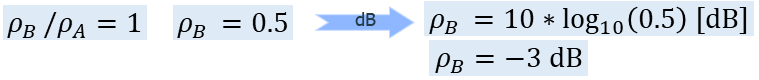
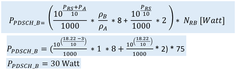
rho B is equal to -3 dB, and the power of PDSCH type B in dBm is given by the formula:

the corresponding value in mWatt is given by :

an other example of rho B calculation:
Pb = 0, Pa = -3dB, and two antenna ports.
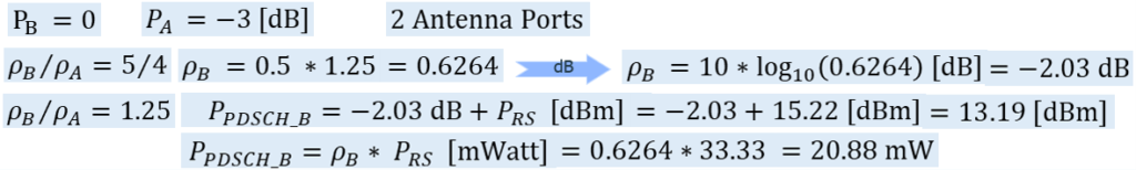
The Calculation result for our example is:
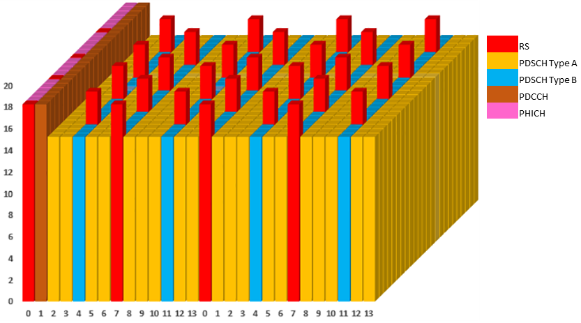
the view of the power level of each channel type.
in this example the PDCCH and PHICH power are equal to the reference signal power.
to calculate the power for PDSCH type A and B in Watt for all RBs, are given by the two formulas, which include the setting of the reference signal power, Pa , Pb, rho A, and rho B values, and the number of resource block in the allocated bandwidth.
for more calculation examples and channel grid with power level, check the following video: