5G NR Control Resource Set (CORESET)
When a device enters the connected state it has obtained information from the PBCH about the control resource set (CORESET) where it can find the control channel used to schedule the remaining system information.
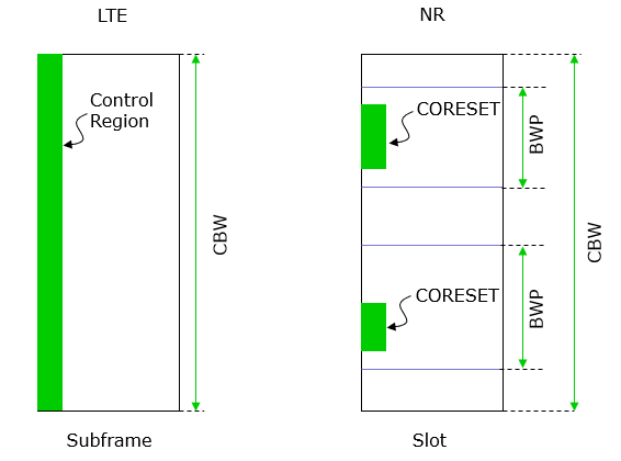
The CORESET configuration obtained from the PBCH also defines and activates the initial bandwidth part in the downlink.
The initial active uplink bandwidth part is obtained from the system information scheduled using the downlink PDCCH.
Once connected, a device can be configured with up to four downlink bandwidth parts and up to four uplink bandwidth parts for each serving cell.
On each serving cell, at a given time instant one of the configured downlink bandwidth parts is referred to as the active downlink bandwidth part for the serving cell and one of the configured uplink bandwidth parts is referred to as the active uplink bandwidth part for the serving cell.
This simplifies the implementation as a single oscillator can be used for both directions.
Initial DL/UL BWP: The initial DL and UL BWPs are used at least for initial access before radio resource control (RRC) connection is established. An initial BWP has index zero and is referred to as BWP #0.
During the initial access, the UE performs cell search based on synchronization signal block (SSB) composed of primary synchronization signal (PSS), secondary synchronization signal (SSS), and physical broadcast channel (PBCH).
To access the system, the UE needs to further read system information block 1 (SIB1) which carries important information including the initial DL/UL BWP configuration.
The SIB1 is transmitted on the PDSCH, which is scheduled by downlink control information (DCI) on the PDCCH using the control resource set with index zero (CORESET #0).
Before the UE reads the SIB1, the UE’s initial DL BWP has the same frequency range and numerology as those of CORESET#0. After reading the SIB1, the UE follows the initial DL/UL BWP configuration in the SIB1 and uses them to carry out random-access procedure to request the setup of RRC connection. The network should configure the frequency domain location and bandwidth of the initial DL BWP in the SIB1 so that the initial DL BWP contains the entire CORESET #0 in the frequency domain.
First active DL/UL BWP: The first active DL and UL BWPs may be configured for a Special Cell (SpCell) or a secondary cell (SCell). In a master cell group (MCG), the SpCell refers to the primary cell (PCell) in which the UE performs the connection (re-)establishment procedure. In a secondary cell group (SCG), the SpCell refers to the primary SCG cell (PSCell) in which the UE performs random access for RRC (re-)configuration. An SCell provides additional radio resources on top of an SpCell in a cell group.
The first active DL and UL BWPs are the active DL and UL BWPs upon RRC (re-)configuration for an SpCell or activation of an SCell.
Default BWP: For a serving cell, the network may configure the UE with a BWP inactivity timer. The expiration of this timer may, for example, indicate that the UE has no scheduled transmission and reception for a while on the currently active BWP. Thus, the UE can switch its active BWP to a default BWP to save power. The default DL BWP can be configured. If not configured, the UE uses the initial DL BWP as the default DL BWP.
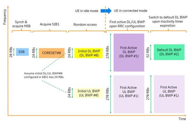
For unpaired spectrum, when the UE switches its active DL BWP to the default DL BWP, the active UL BWP is switched accordingly since the BWP switching for TDD is common for both DL and UL. The Figure provides an illustration of the aforementioned BWP types from a UE processing perspective.
The UE first performs downlink synchronization and acquires PBCH based on 20-RB SSB. Assuming the CORESET#0 configured in the MIB has 24 RBs, the UE may assume that the initial DL BWP is 24 RBs wide and proceeds to acquire SIB1, which in this example also configures 24 RBs for both initial DL and UL BWPs.
The UE then performs random-access procedure with the small initial DL and UL BWPs. After the random access, the UE reports that it is capable of supporting multiple BWPs. With dedicated RRC signaling, the network configures the UE with large DL/UL BWP #1 (270 RBs), small DL/UL BWP#2 (52 RBs), and BWP inactivity timer.
The network sets the large DL/UL BWP #1 as the first active DL/UL BWP, and the small DL BWP #2 as the default DL BWP. Upon RRC configuration, the first active DL and UL BWPs (i.e., DL/UL BWP #1) become activated and are used for scheduling a large amount of data. After that, the UE does not have traffic demand and has no scheduled transmission. As a result, the BWP inactivity timer expires, upon which the UE switches its active DL BWP to the default DL BWP (i.e., DL BWP #2). Note that the active UL BWP does not need to switch to UL BWP #2, because the Figure illustrates an FDD system in which DL and UL BWPs are switched separately.
")


