Common Resource Blocks & Physical Resource Blocks
NR, supports multiple numerologies and, not all devices may support the full carrier bandwidth. Therefore, the notion of two types of resource blocks, common resource blocks and physical resource blocks, are used.
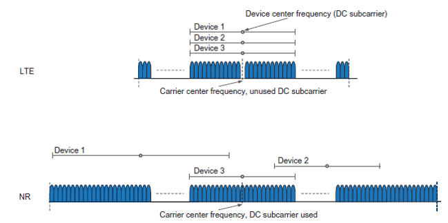
However, the device needs to know where in the carrier the resource blocks are located.
In LTE, where there is a single numerology and all devices support the full carrier bandwidth, this is straightforward.
NR, on the other hand, supports multiple numerologies and, as discussed further below in conjunction with bandwidth parts, not all devices may support the full carrier bandwidth.
Therefore, a common reference point, known as point A, together with the notion of two types of resource blocks, common resource blocks and physical resource blocks, are used.
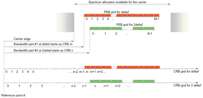
Reference point A coincides with subcarrier 0 of common resource block 0 for all subcarrier spacings.
This point serves as a reference from which the frequency structure can be described and point A may be located outside the actual carrier.
Upon detecting an SS block as part of the initial access, the device is signalled the location of point A as part of the broadcast system information (SIB1).
The physical resource blocks, which are used to describe the actual transmitted signal, are then located relative to this reference point.
For example, physical resource block 0 for subcarrier spacing Δf is located m resource blocks from reference point A or, expressed differently, corresponds to common resource block m.
Similarly, physical resource block 0 for subcarrier spacing 2Δf corresponds to common resource block n. The starting points for the physical resource blocks are signaled independently for each numerology (m and n in the example).
")


")
